The spur gear design formula is crucial for engineers and designers who seek to create efficient gear systems.
This article will explore the essential elements of spur gear design, the formula itself, and its applications in various fields.
What Is a Spur Gear?
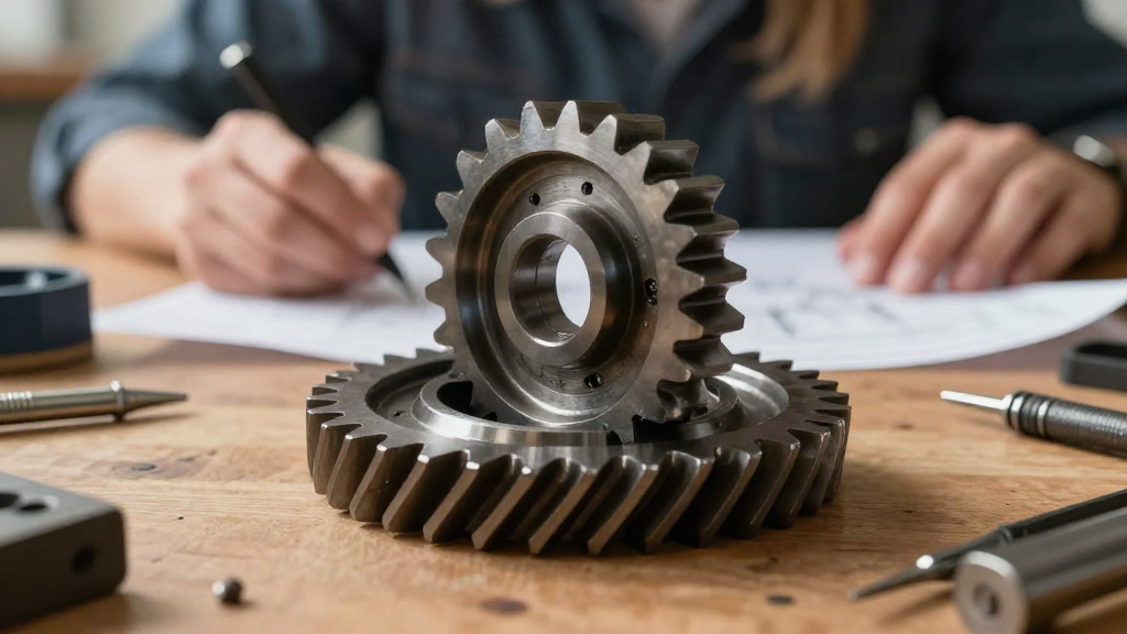
A spur gear is a cylindrical gear characterized by its straight teeth, which are parallel to the gear’s axis.
These gears are used for transmitting power and motion between parallel shafts.
Key Characteristics of Spur Gears:
- Efficiency: Spur gears are highly efficient in transferring torque and motion.
- Simple Design: Their uncomplicated manufacturing process makes them cost-effective.
- Low Noise: They generate relatively low noise levels compared to other gear types, especially when operating at lower speeds.
Understanding these characteristics is important for leveraging the spur gear design formula effectively.
What Is the Spur Gear Design Formula?
The spur gear design formula is a mathematical expression used to determine important design parameters of spur gears.
It typically involves several key components:
- Pitch Diameter (D): The diameter at which the gear teeth engage.
- Number of Teeth (N): The total number of teeth on the gear.
- Module (m): A measure of tooth size, defined as the pitch diameter divided by the number of teeth.
The basic formula can be expressed as follows:
[ D = m \times N ]
Where:
– ( D ) = Pitch Diameter (in mm or inches)
– ( m ) = Module
– ( N ) = Number of Teeth
Related Formulas:
In addition to the basic formula, several other factors are essential to spur gear design:
-
Center Distance (C): The distance between the centers of two gears
[ C = \frac{{D_1 + D_2}}{2} ] -
Gear Ratio (GR): The ratio of the number of teeth on two meshing gears
[ GR = \frac{{N_2}}{{N_1}} ]
Where ( N_1 ) and ( N_2 ) are the number of teeth on the first and second gears respectively.
How to Apply the Spur Gear Design Formula?
To utilize the spur gear design formula, follow these steps:
-
Determine Design Requirements: Identify power transmission needs, including load, torque, and speed.
-
Select Module: Choose an appropriate module based on material selection and gear size limitations.
-
Calculate Number of Teeth: Use the formula ( N = \frac{D}{m} ) to determine the number of teeth required for the desired pitch diameter.
-
Calculate Center Distance: For multiple gears, calculate the center distance using the center distance formula.
-
Check Compatibility: Verify that the calculated parameters suit existing designs or specifications in terms of backlash and tooth strength.
What Factors Affect Gear Design?
Several factors influence the selection of the spur gear design formula:
1. Material Selection:
- Strength: Materials like steel, aluminum, and composite materials possess different strength-to-weight ratios.
- Durability: Consider wear resistance and the environment in which the gear will operate.
2. Load Application:
- Dynamic Loads: Determine the load types affecting the gear throughout its operation.
- Static Loads: Assess the maximum static load the gear must endure without yielding.
3. Speed:
- Rotational Speed: Higher speeds can create additional stress and heat, requiring specific design adjustments.
- Harmonics: Consider potential vibration and noise at various operational speeds.
4. Manufacturing Constraints:
- Tolerance: Ensure tolerances in the manufacturing process meet the necessary operational specifications.
- Machining Process: Different materials require different manufacturing techniques (hobbing, shaping, etc.).
Why Is the Spur Gear Design Formula Important?
The spur gear design formula is important for several key reasons:
1. Enhancing Efficiency:
- A well-optimized spur gear can significantly reduce energy losses during operation.
- Efficiency leads to better performance and lower operational costs.
2. Ensuring Reliability:
- Proper calculations minimize the risk of gear failure due to overstressing or improper sizing.
- Reliable gears improve overall system durability.
3. Improving Performance:
- Accurate design parameters directly correlate to smoother operation and better torque transfer.
- High-performance gears can handle higher loads without increasing size.
4. Cost Effectiveness:
- Smart design choices allow manufacturers to produce gears that meet performance requirements without unnecessary material wastage.
- Efficient designs save costs in materials and labor during production.
Common Applications of Spur Gears
Spur gears are ubiquitous in various industries. Some common applications include:
- Automotive: Used in transmissions and differentials.
- Aerospace: Found in actuators and flight control systems.
- Industrial Machinery: Employed in conveyor systems and automation.
- Robotics: Used in robotic arms and motion systems.
- Consumer Products: Common in everyday appliances such as washing machines and food processors.
What Are the Limitations of the Spur Gear Design Formula?
While the spur gear design formula is immensely useful, there are limitations:
1. Limited to Parallel Shafts:
The spur gear design is only applicable for gears on parallel shafts, limiting versatility.
2. Non-Optimal for High-Speed Applications:
At very high speeds, spur gears can be noisier than helical gears, making them less favorable in certain applications.
3. Backlash Issues:
Tooth clearance can lead to backlash, which may affect performance in precision applications.
Conclusion
The spur gear design formula is an invaluable tool for engineers and designers.
Understanding how to effectively use this formula allows for the creation of reliable, efficient, and cost-effective gear systems.
By considering various factors during the design process, one can ensure optimized performance that meets application demands in different industries.
Whether you are designing for automotive applications or complex industrial machinery, a solid grasp of spur gear dynamics will lead to greater success in your projects.