Whether you are interested in creating your own mechanical designs or simply want to understand the basics, this gear CAD tutorial is the perfect starting point.
In this guide, we’ll walk you through the fundamental concepts and tools you’ll need to create gear designs using Computer-Aided Design (CAD) software.
What is CAD and Why Use It for Gears?
Computer-Aided Design (CAD) is a technology used to create, modify, analyze, or optimize designs.
When it comes to gears, using CAD software offers several advantages:
- Precision: Achieve high levels of accuracy that are often difficult with manual methods.
- Flexibility: Easily make changes or experiment with different designs.
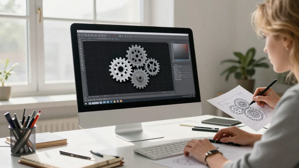
- Visualization: Clearly see and analyze how gears fit together within a larger mechanical system.
- Simulation: Test the functionality of your gear designs prior to manufacturing.
Having a good grip on CAD principles can greatly enhance your gear design process.
Which CAD Software Should I Choose?
Choosing the right CAD software for your gear designs is essential.
Here are some popular CAD software packages you might consider:
- AutoCAD
– A robust tool preferred by many professionals. - SolidWorks
– Ideal for 3D modeling and simulations. - Fusion 360
– A versatile, cloud-based option suitable for beginners. - FreeCAD
– A free, open-source program that caters to a range of design needs.
In our gear CAD tutorial, we will discuss concepts that can be applied universally, but specific tools might vary depending on the software you choose.
How Do You Start Designing Gears in CAD?
Starting with gear design can be overwhelming, but breaking it down into steps can simplify the process.
Here’s a simple step-by-step guide to get you started:
-
Open Your CAD Software
– Start a new project or drawing. -
Set Up Your Units
– Ensure you are working with the correct measurement units (inches, millimeters, etc.). -
Select Gear Design Tools
– Use built-in gear generators or gear templates to help create your design. -
Define Gear Parameters
– Set parameters such as:- Number of Teeth
- Pitch Diameter
- Pressure Angle
-
Create a Gear Profile
– Use the software’s drawing tools to sketch out your gear profile. -
Extrude the Profile
– Convert your 2D gear sketch into a 3D model. -
Add Necessary Features
– Include features like holes or keyways as required for your specific design. -
Save Your Design
– Don’t forget to save your work frequently!
These steps provide a solid foundation for your first gear design in CAD.
What Gear Design Concepts Should I Understand?
To excel in your gear design efforts, it’s important to grasp several key concepts.
Here are the foundational concepts every beginner should know:
-
Type of Gears: Understand the types of gears (spur, bevel, worm, etc.) that you might want to design.
-
Gear Ratios: A critical concept, gear ratios dictate how rotational speed and torque are altered in gear systems.
-
Involute Profile: The shape of the gear tooth is essential for proper meshing.
-
Clearance and Backlash: These aspects ensure that gears operate smoothly without binding.
Familiarizing yourself with these concepts will aid your understanding as you progress through this gear CAD tutorial.
How Do I Use CAD Software to Create Gears?
Now that you know the foundational concepts, let’s dive into creating a gear using CAD software.
Here’s an example workflow using a gear generator tool in your CAD software:
-
Open Gear Generator Tool
– Look for the gear generator tool in your software’s menu. -
Input Gear Parameters
– Enter specifications such as:- Number of Teeth
- Module/DP (Diametric Pitch)
- Pressure Angle
-
Generate the Gear
– Click ‘Generate’ or a similar command to create the gear model. -
Modify as Needed
– Sculpt or modify the generated gear based on your design requirements. -
Save and Export
– Save your gear as a CAD file and export it as needed for further use or 3D printing.
This workflow serves as a practical application of your gear CAD tutorial knowledge.
How Can I Make My Gears More Functional?
Making your gears more functional often involves additional design considerations.
Here are a few tips to enhance your gear performance:
-
Material Choice: Select materials that will resist wear and tear based on your application’s requirements.
-
Surface Treatment: Implement coating or treatment to improve durability.
-
Lubrication Design: Design spaces for easy lubrication to prolong gear life.
Incorporating these elements into your design will help achieve optimal functionality.
Where Can I Find Additional Resources for Gear Design?
As you explore more about gear design and Computer-Aided Design, you might want to look for additional resources.
Here are some recommendations:
-
Online Courses: Platforms like Coursera and Udemy offer specialized courses on CAD software and mechanical design.
-
Forums and Communities: Engaging in forums like Reddit, CADTutor, or GrabCAD can provide you with practical advice from other users.
-
YouTube Tutorials: Numerous channels specifically focus on CAD tutorials and gear design.
These resources can supplement your learning and provide further insight into complex gear design topics.
Conclusion
This gear CAD tutorial has provided you with a roadmap for starting your journey in gear design using CAD software.
By understanding key concepts, selecting the right tools, and following structured steps, you can create functional and precise gear models.
Don’t forget to continue learning and practicing.
Each gear you design will enhance your skills and confidence in the world of CAD.
Happy designing!