When it comes to technical drawings and engineering schematics, understanding the meaning of various symbols is paramount for effective communication. One of the most commonly encountered elements in these drawings is gear symbols in drawings.
In this article, we will explore what gear symbols mean, why they matter, and how they are used in engineering and design.
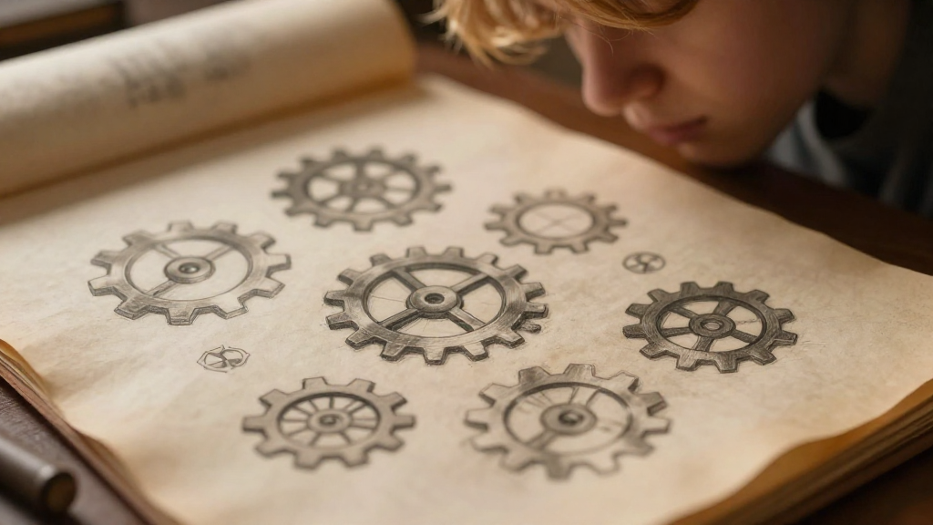
What Are Gear Symbols in Drawings?
Gear symbols in drawings represent mechanical gears, which are essential components in various machines and devices.
These symbols convey critical information about gear features, such as:
- Type of gear (e.g., spur, helical, bevel, etc.)
- Size and dimensions
- Tooth count
- Material specifications
Understanding these symbols is vital for engineers, designers, and anyone involved in mechanical design.
Why Are Gear Symbols Important?
What Role Do Gear Symbols Play in Design?
Gear symbols serve several essential functions in mechanical drawings:
-
Clarity: They provide a quick reference for identifying gear types and specifications without lengthy descriptions.
-
Standardization: Using standardized gear symbols promotes uniformity and reduces misinterpretation among engineers and technicians.
-
Efficiency: They streamline the communication process, allowing designers to convey complex designs with relative ease.
-
Preventing Errors: Misunderstanding gear specifications can lead to significant mechanical failures. Accurate symbols help mitigate these risks.
How Are Gear Symbols Used in Various Industries?
Where Are Gear Symbols Commonly Found?
Gear symbols in drawings are prevalent in several industries, including:
-
Automotive Engineering: For depicting gear systems in transmissions and drive trains.
-
Aerospace Engineering: In jet engines and control systems to illustrate intricate gear assemblies.
-
Manufacturing: In the design of machinery and tools that require precise gear interactions.
-
Robotics: Where understanding gear relationships is crucial for movement and functionality.
Each industry might favor specific styles of gear symbols, but their core meaning remains consistent.
What Do Different Gear Symbols Represent?
Are There Universal Gear Symbols?
While there are several styles of gear symbols, specific conventions are widely accepted in engineering.
The primary types of gear symbols in drawings include:
-
Spur Gear: Depicted by two parallel lines or an enclosed circle with radial lines representing teeth.
-
Helical Gear: Similar to spur gears but with an angle indicated to show the helical nature of the teeth.
-
Bevel Gear: Illustrated with an angled line or triangle, indicating a change in shaft direction.
-
Worm Gear: Represented as a helical line around a circle, typically signifying a gear that drives another at a right angle.
-
Rack and Pinion: Indicated by a rectangle (rack) paired with a circle (pinion).
These symbols often come with accompanying dimensions or notes to clarify their size, material, or other operational parameters.
How to Read Gear Symbols in Drawings?
What Should You Look For?
When interpreting gear symbols in drawings, everyone involved in the design process should pay attention to several aspects:
-
Symbol Shape: Identify the basic shape of the gear symbol to determine the gear type.
-
Dimensions: Look for any accompanying numbers detailing gear size, pitch, and other critical measurements.
-
Annotations: Examine any notes or legends that accompany the symbols. These could provide context or additional details about the gear function.
-
Connection Lines: Observe the lines connecting gear symbols to other elements of the drawing. They indicate how the gears interact with other components.
By taking the time to analyze these details, you can gain a clearer understanding of the intended design and functionality.
How to Create Effective Gear Symbols in Drawings?
What Best Practices Should You Follow?
When creating gear symbols in drawings, following best practices can enhance clarity and effectiveness:
-
Use Standardized Symbols: Familiarize yourself with the accepted standards for gear symbols in your industry to ensure uniformity.
-
Keep it Simple: Avoid overcrowding the drawing with too much information. Focus on essential details.
-
Leverage Color Coding: Consider using colors to distinguish between different types of gears or their functions—this can make the drawing easier to read.
-
Provide Legends: Include a legend or key in your drawings to clarify less common symbols or unique specifications.
-
Review and Revise: Always review your drawings with peers to catch potential misunderstandings or errors.
By adhering to these practices, you can create clearer and more effective engineering drawings.
Where Can You Learn More About Gear Symbols?
What Resources Are Available?
To deepen your understanding of gear symbols in drawings, numerous resources are at your disposal:
-
Engineering Textbooks: Books on mechanical design often include detailed sections on technical drawing and symbols.
-
Online Courses: Platforms like Coursera or LinkedIn Learning offer courses on technical drawing and engineering design.
-
Industry Standards: Organizations like ANSI (American National Standards Institute) or ISO (International Organization for Standardization) provide guidelines on engineering symbols.
-
Professional Workshops: Attending workshops or seminars can also offer practical, hands-on training.
Engaging with these resources not only enriches your knowledge but also keeps you updated on industry practices.
Final Thoughts on Gear Symbols in Drawings
Understanding gear symbols in drawings is fundamental for engineers, designers, and anyone involved in mechanical design.
These symbols play a critical role in communicating design intentions, preventing misunderstandings, and ensuring efficiency in the manufacturing process.
By knowing how to read and create these symbols effectively, you can contribute to successful engineering projects and promote better collaboration across teams.
In a field where precision is paramount, every detail counts.
Keep this guide handy, and make sure to reference it when working with gear symbols in your future projects!